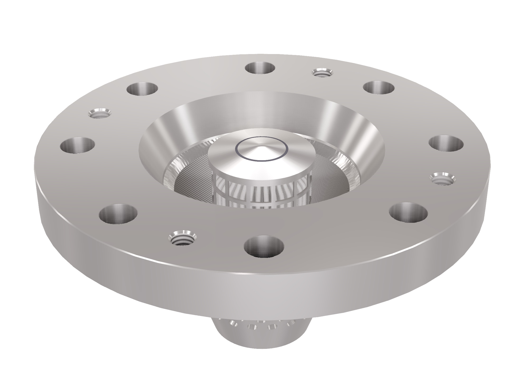
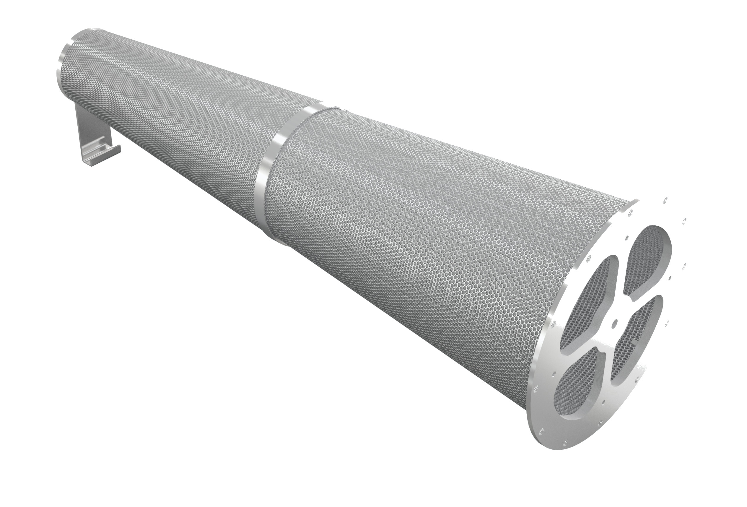
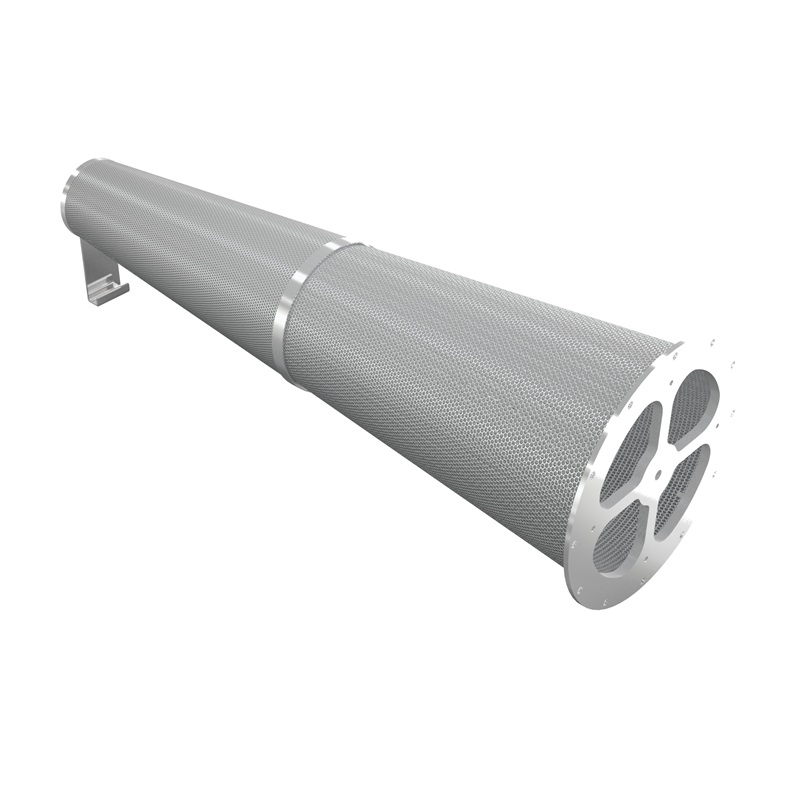
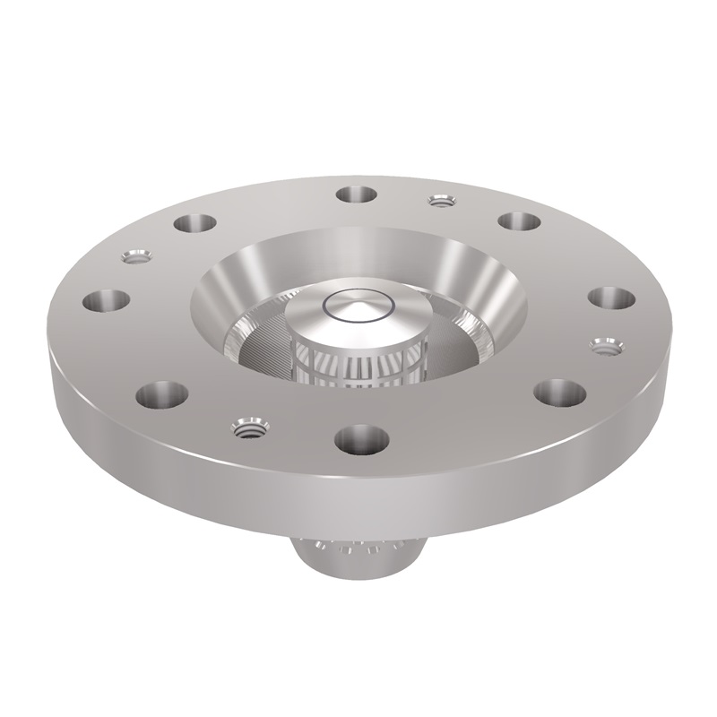
Supercritical CO2 Sealing Q&A: Your Top Questions From Our CCUS Webinar

22 April 2024

5 Minute Read

Last month, John Crane partnered with Turbomachinery International to host the webinar, “Sealing the Future: Using Innovation to Accelerate CCUS.” If you watch one CCUS webinar, make it this. Interactive and immersive, the webinar covered a much-discussed topic in new energy: the sealing challenges posed by supercritical CO2 (sCO2). The webinar ended with a Q&A session that uncovered key insights into the role of sCO2 sealing solutions in accelerating CCUS deployment.

To support you along your CCUS journey, we’ve compiled the Q&A topics covered during the webinar — plus insights into secondary seals, the role of R&D and more.

Q: What are the major differences in seals and sealing systems for sCO2 compressor applications?

A: In terms of design, there is no major difference when dealing with gaseous CO2. The difference is mainly in how we approach the problem from the mating curvature and groove profile ring design and groove perspective. From a CO2 perspective, in the gaseous phase, operators would mainly use our Type 28EXP dry gas seal technology. At higher pressures, applications could require Type 28EXP.

Q: Please revisit the fertilizer plant case study you shared, specifically related to thermal management and the dry gas seal model for sCO2. What were the key learnings, and which dry gas seal technology was used? 

A: In that case study, we used Type 28XP. The phase was specifically supercritical. The machine had eight stages, and we were sealing the last two or three stages. This is a good example of the value of collaboration among an end-user, compressor OEM and ourselves — all working in tandem to provide a robust solution to the customer.

This brings us to temperature. In all these sCO2 applications, we are facing high temperatures. However, these critical points and supercritical points are in the “normal operation area” of a dry gas seal. The fact that we are talking about a pressure and temperature range that is quite normal for other gasses makes CO2 sealing so special. These high-temperature requests, especially with new power cycles, are challenging. 

The challenge doesn’t lie with the sealing technology itself; we have a groove design and a lift-off. With the secondary sealing elements, we still have a long way to go. It’s too early to give a clear direction on how to proceed just yet.

Q: How do you prevent dry ice formation when the pressure is dropping across the seal faces?


A: When we’re dealing with CO2, leakage is critical. The Joule-Thomson cooling effect will be exacerbated by the leakage between the primary ring and mating ring. This will then gradually shift the application point toward the left of the phase diagram. 

We have two ways to combat that. First, minimize leakage through the design of the seal — i.e. primary and mating ring design. In instances where this is not possible, John Crane usually suggests the addition of a heater, which ensures the conditioning of the gas to avoid unwanted phase change.

Q: Are elastomers used for secondary seals in CO2 applications? If so, what are the concerns about mitigating failure due to decompression?

A: For gaseous CO2, and to combat the risk of explosive decompression, we would aim to deploy an XP or EXP type seal, aligned with pressure requirements. These seals would offer spring energized polymers as a secondary sealing solution. This, in turn, would mitigate against  any risk of explosive decompression.

Q: What purity levels are normally assessed for CO2?

A: The purity levels are the same as other gasses. This is related to the other question about filtered process gas. We always recommend having pure gas in front of the seal to avoid contamination, whether it’s in liquid form, droplets or vapor. We recommend purity smaller than 3 microns. The gap in the dry gas seal is approximately 4 microns, which is one-10th of the thickness of hair — very small. The particles in front of the seal should be smaller than the gap to avoid scratches and other issues. 

Q: For applications involving tandem seals with filtered process gas for the primary seal gas, do you always need a backup source to feed your primary seal gas for startup and shutdown? If not, how do you assess the need for it?

A: Not necessarily. It can be from the discharge of the compressor as well. However, we have to look into a project’s complete environment to provide advice. It’s not easy to offer a global approach because many project-specific factors can influence the need for a backup source. 

Q: What is the maximum decompression rate that Type 28XP and Type 28VL seals can withstand?

A: As an order of magnitude, we can say it’s roughly around 100 bar per minute for polymers as a secondary sealing solution, which are found in John Crane’s Type 28XP range. However, this is quite specific to the application. For example, if O-rings are deployed, which is the case in our Type 28VL seals, then this value would be around 20 bar per minute.

Q: For sCO2 applications on compressors, what is the current end-user market split for carbon ring seals versus dry gas seals?

A: The market split is currently changing. One of the points at the beginning of the presentation was that CO2 is part of our air. In the past, end-users did not really consider the amount of leakage; their priority was using technology to seal the compressor itself. There was a split at around 40 bar, where they changed from carbon ring designs to dry gas seal designs due to the amount of carbon rings they had to use in a cartridge. This was, until now, the reason for the split between carbon ring and dry gas seals. If we handle CO2 as a product itself that we want to keep inside — which we want to store as much as possible and not let disappear into the environment — then the dynamic changes. We have to consider that carbon rings leak much more than dry gas seals. For this reason, we are seeing more interest in sealing CO2 at lower pressures using dry gas seals that limit leakage.

We spoke earlier about tandem seals, which are capable of sealing more and leaking less than a single seal. However, it’s often a decision for the compressor’s OEM whether to go with the single seal, which will have the same sealing capabilities and inboard stage as a tandem seal. However, they also have to consider other elements — the overhang moment, for example — and sometimes decide to proceed with a single seal design rather than a tandem seal design.

Q: What components are critical to a seal gas conditioning system? 

A: Although the system itself uses either seal gas or processed gas from the discharged side or an external source, we recommend a double filter. This allows uninterrupted flow toward the seal. You also have elements such as the pressure control valve and, often, different ways of flow control such as a variable area or flow meter or an orifice to set up the flow. We will provide the seal leakage to customers, but through interaction with the compressor OEM, we know the leakage toward a process. We can set up the flow level that we expect in front of the seal using flow meters. 

If necessary, we can also provide the heater. The filter elements can also vary. If we expect vapor, then we can use coalescer filters that remove vapor from the gas. In terms of the style and components of the dry gas seal system, these are the same as normal seal systems.

Q: What is the maximum operating temperature? Does John Crane offer any conditioning equipment to help cool down gas?

A: The design of our seals is robust enough to perform reliably up to 200°C, though we wouldn’t recommend it. New applications such as the Allam power cycle feature extremely high temperatures. But as of now, in my experience, we haven’t seen many applications with extremely high temperatures, except for these new power cycle applications. 

Discussions about seal gas temperature always have to consider heat generation within the seal. At the end of the day, the design temperature of the seal will always be a little bit higher than the seal gas temperature in front of the seal because we have to respect heat generation within the seal. We have a safety margin which is about 30 to 40 Kelvins difference.

Q: What are the concerns around corrosion? How are you mitigating them?

A: From a material perspective, we would always deploy the correct and suitable materials,  aligned with NACE requirements. All our materials would be some version of stainless steel alloy that would account for the possible presence of corrosive elements, through impurities within the process gas. From my perspective, we have already mitigated corrosion risks. There is nothing novel about this. 

Q: Where are John Crane’s CO2 seals for CCUS applications available and what are the expectations in receiving the products and support? What should we keep in mind from the perspective of procurement, lead time and sparing philosophy? 

A: We have three centers, which are in Japan, the U.K., and North America in Chicago. All these centers manufacture seals for CO2 applications. In principle, these seal technologies do not differ from our other dry gas seals in our portfolio. There are no specific parts that differentiate them from other dry gas seals. For that reason, our manufacturing capabilities are not restricted to certain regions or manufacturing facilities. There is also no difference in terms of lead times, procurement and sparing philosophy. Whether you want to purchase a seal for a nitrogen application, hydrogen application or nitrogen gas application, supply and support are the same. 

Accelerate Your Progress With John Crane Today

For nearly 30 years, John Crane has equipped CCUS operations with safe, reliable solutions. Our unrivaled track record includes a quarter-century of expertise in supercritical CO2 sealing — one of the most critical challenges in scaling carbon capture deployment. Contact our experts today to discuss your CCUS initiative, and view our webinar on-demand for more insights into CO2 sealing innovation. We’re here to help you maximize reliability and sustainability in the new energy era.

Scroll to top